




5 Axis Gantry
Product Details
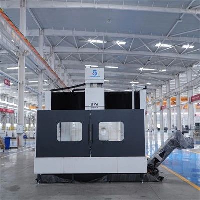
The GBX-4240U 5 axis gantry machine tool features an elevated bridge-type structure with a stationary worktable. Longitudinal saddles are mounted on the left and right bed sections, jointly supporting a "box-in-box" style crossbeam that moves along the X-axis. The entire machine utilizes an enclosed frame structure, ensuring high rigidity.
Machine Specifications
|
Item |
Unit |
Parameters |
|
Worktable |
||
|
Table size |
mm |
3000×4000 |
|
Max. table load |
kg/m² |
8000 |
|
T-slot width × pitch |
mm |
28×250 |
|
Machining Range |
||
|
Distance between columns (clearance) |
mm |
4200 |
|
Spindle nose to table surface |
mm |
200-1450 |
|
X/Y/Z axis travel |
mm |
4200/3000/1250 |
|
Speed |
||
|
X/Y/Z axis rapid traverse |
m/min |
30/30/20 |
|
Cutting feed rate |
m/min |
20 |
|
AC Swivel Head (Torque Motor Direct Drive) |
||
|
Brand / Model |
- |
Mepro T70-200 |
|
A/C axis max. swivel speed |
rpm |
60/60 |
|
A/C axis max. torque |
N.m |
1060/1350 |
|
A/C axis rated torque (S1-100%) |
N.m |
700/715 |
|
A/C axis braking torque |
N.m |
4000/4000 |
|
A/C axis positioning accuracy |
arc.sec |
8"/8" |
|
A/C axis swivel range |
deg |
±105°/±360° |
|
Spindle |
||
|
Spindle taper |
- |
HSK-A100 |
|
Spindle speed range |
rpm |
Rated 2580 / Max. 10000 |
|
Spindle power (S1-100%) |
kW |
54 |
|
Spindle torque (S1-100% / S6-40%) |
N.m |
200 / 240 |
|
Drive & Guideway |
||
|
X/Y axis drive type |
- |
Alpha gear rack |
|
Z axis ballscrew spec. |
- |
6340 |
|
X/Y/Z axis guideway type |
- |
4-55 heavy-duty roller guideways |
|
Control System |
||
|
CNC system |
- |
Siemens SIEMENS ONE |
|
Machine Accuracy (in accordance with GB/T33150-2016) |
||
|
Positioning accuracy (X/Y/Z) |
mm |
0.023/0.023/0.012 |
|
Repeatability (X/Y/Z) |
mm |
0.018/0.018/0.01 |
|
Others |
||
|
Power supply requirement |
kVA |
150 |
|
Air pressure requirement |
Kg/cm² |
6-8 |
|
Floor space approx. (L×W×H) |
m |
8×7.8×6 |
Product Details
Symmetrical "Box-in-Box" Crossbeam
The Y-axis crossbeam features a symmetrical "box-in-box" design, with the ram nested inside an outer box structure; the spindle centerline aligns precisely with the central axis of both the crossbeam and the ram. When workshop temperatures fluctuate (e.g., a difference of over ten degrees between summer and winter), the crossbeam and ram undergo synchronous thermal expansion and contraction. Thanks to the symmetrical structure, the shift in the spindle centerline is minimal, resulting in machining accuracy that is less affected by ambient temperature compared to asymmetrical designs.
Torque Motor Direct-Drive AC Swivel Head
Equipped with an Ibag Mepro T70-200 five-axis milling head, the A and C axes are directly driven by individual torque motors. This non-contact drive system eliminates intermediate components such as gears, worm gears, or belts. Key advantages include zero backlash (maintaining accuracy during reversals), long-term stability due to the absence of mechanical wear, and superior surface finish resulting from the lack of gear-mesh vibration and noise. With a braking torque of 4000 N·m, the head locks securely without sagging during power outages or emergency stops.
Spindle Temperature Control System
The spindle is equipped with a cooling unit that circulates coolant around the spindle's outer housing to dissipate heat generated during high-speed rotation. Bearings utilize oil-mist lubrication, providing simultaneous lubrication and cooling. Internal temperature sensors trigger an alarm if the temperature exceeds the set range, preventing spindle damage due to overheating.
Four-Rail Configuration for All Three Axes
The X, Y, and Z axes are each equipped with four heavy-duty 55-series roller guideways. The X-axis features two rails on each of the left and right bed sections; the Y-axis crossbeam has four rails distributed at equal intervals; and the Z-axis ram has one rail on each of its four faces. This configuration provides a wide load-bearing surface and reduces the load on individual slide blocks, ensuring smooth motion.
Ram with Four-Rail Configuration
The ram utilizes a square configuration with four roller guideways-one on each face-providing a large effective guiding length. When the ram extends 1250mm for machining, all four guideways provide simultaneous guidance and load support. Cutting forces are distributed across four directions, minimizing ram oscillation and ensuring stable cutting. This design offers superior rigidity compared to configurations using only two diagonally opposed guideways.
Cooling and Chip Removal System
The system employs external cooling. Screw-type chip conveyors are installed on both sides of the machine bed to collect chips generated during machining and transport them to a slat-type chip conveyor located at the front of the machine; the slat conveyor then discharges the chips into a collection cart positioned to the side. Once collected, the chips can be easily wheeled away and dumped, eliminating the need for manual pit cleaning.


Product Applications
- Aerospace aluminum alloy structural parts: Integral thin-walled components such as aircraft wing ribs, frame beams, and skin panels.
- Large automotive body panel molds: Stamping molds for car doors, roofs, side panels, etc.
- Energy equipment impellers and diffuser casings: Compressor impellers, pump diffuser casings, etc.
- Composite material components: Carbon fiber aerospace parts, wind turbine blade molds, and other non-metallic components.
- Large frame-type parts: Castings such as robot bases, machine tool columns, etc.

After-Sales Service

Foundation and installation preparation: Prior to equipment arrival, the customer must complete foundation construction and secondary grouting (with concrete curing for at least 28 days) in accordance with foundation drawings. Consumables (coolant, hydraulic oil, guideway oil, lubricating grease, etc.) are to be provided by the customer.
Unloading and positioning: The customer is responsible for unloading, hoisting, and positioning the equipment. Before shipment, the manufacturer provides the equipment's overall dimensions, weight, center of gravity, and a hoisting diagram.
Installation and commissioning: Once positioned, the customer notifies the manufacturer to dispatch commissioning personnel. Before the personnel arrive, the customer must complete the connection of the power supply (3-phase 380V/50Hz, 150kVA) and air supply (6–8 kg/cm²), but must not activate the power or air supply beforehand. The customer signs a confirmation upon completion of commissioning.
Warranty period: 12-month warranty for the entire machine (starting from the date of successful acceptance); repairs and part replacements due to quality issues are free of charge during the warranty period.
After-sales response: Telephone response within 24 hours of a service request; spare parts supplied at cost price after the warranty period expires.
Hot Tags: 5 axis gantry, China 5 axis gantry manufacturers, suppliers, factory
You Might Also Like



Send Inquiry