



Elevated Bridge 5 Axis Gantry Machining Center
Product Details
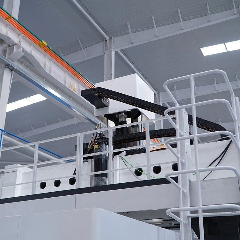
The GBX-3530U employs an elevated bridge-style structure featuring a stationary worktable fixed to the ground. Longitudinal saddles are mounted on the left and right bed sections, jointly supporting a "box-in-box" crossbeam; the crossbeam, along with the ram it carries, moves along the X-axis. Compared to traditional moving-gantry designs, this configuration is more compact, offers a large cross-sectional area and superior torsional rigidity for the crossbeam, and ensures a low center of gravity for moving components. Major castings-including the bed, saddles, crossbeam, carriage, and ram-are made of high-strength cast iron using the resin sand molding process, providing excellent vibration damping and thermal stability.
|
Item |
Unit |
Parameters |
|
Worktable |
||
|
Table size |
mm |
2500×3000 |
|
Max. table load |
kg/m² |
8000 |
|
T-slot width × pitch |
mm |
28×250 |
|
Machining Range |
||
|
Distance between columns (clearance) |
mm |
3500 |
|
Spindle nose to table surface |
mm |
200-1450 |
|
X/Y/Z axis travel |
mm |
3200/2500/1250 |
|
Speed |
||
|
X/Y/Z axis rapid traverse |
m/min |
30/30/20 |
|
Cutting feed rate |
m/min |
20 |
|
AC Swivel Head (Torque Motor Direct Drive) |
||
|
A/C axis max. swivel speed |
rpm |
60/60 |
|
A/C axis max. torque |
N.m |
1060/1350 |
|
A/C axis rated torque (S1-100%) |
N.m |
700/715 |
|
A/C axis braking torque |
N.m |
4000/4000 |
|
A/C axis positioning accuracy |
arc.sec |
8"/8" |
|
A/C axis swivel range |
deg |
±105°/±360° |
|
Spindle |
||
|
Spindle taper |
- |
HSK-A100 |
|
Spindle speed range |
rpm |
Rated 2580 / Max. 10000 |
|
Spindle power (S1-100%) |
kW |
54 |
|
Spindle torque (S1-100% / S6-40%) |
N.m |
200 / 240 |
|
Drive & Guideway |
||
|
X/Y axis drive type |
- |
Alpha gear rack |
|
Z axis ballscrew spec. |
- |
6340 |
|
X/Y/Z axis guideway type |
- |
4-55 heavy-duty roller guideways |
|
Control System |
||
|
CNC system |
- |
Siemens SIEMENS ONE |
|
Machine Accuracy (in accordance with GB/T33150-2016) |
||
|
Positioning accuracy (X/Y/Z) |
mm |
0.02/0.02/0.012 |
|
Repeatability (X/Y/Z) |
mm |
0.015/0.015/0.01 |
|
Others |
||
|
Power supply requirement |
kVA |
150 |
|
Air pressure requirement |
Kg/cm² |
6-8 |
|
Floor space approx. (L×W×H) |
m |
6.8×6.8×6 |
Product Details
"Box-in-Box" Crossbeam Design
The crossbeam features a "box-in-box" design-essentially a smaller square tube nested within a larger square tube, connected by internal reinforcing ribs. Compared to a solid rectangular beam of the same weight, this structure offers superior rigidity and torsional resistance. Left and right carriages support the beam from either end; during X-axis movement, they are driven synchronously, ensuring balanced load distribution.
Four-Guide-Rail Configuration Across All Three Axes
Each of the X, Y, and Z axes is equipped with four heavy-duty 55-series roller guide rails. The X-axis features two rails on each side of the bed; the Y-axis (crossbeam) has four rails spaced evenly; and the Z-axis (ram) has one rail on each of its four sides. This four-rail configuration provides a wider load-bearing surface and distributes forces more effectively; individual slide blocks bear less load, resulting in minimal vibration during movement.
AC Swivel Head with Direct-Drive Torque Motors
The AC swivel head utilizes IBAG Mepro torque motors. Both the A and C axes are directly driven by these motors, eliminating the need for gears, worm gears, or belts. This design offers several advantages: zero backlash during reversals (no transmission clearance), long-term precision stability (no gear wear), and rapid response with excellent path-following accuracy during 5-axis simultaneous contouring. It features a positioning accuracy of 8 arc-seconds and a braking torque of 4,000 Nm, ensuring the head does not sag during power outages or emergency stops.
HSK-A100 Spindle (10,000 rpm)
The HSK-A100 tool interface utilizes dual-contact technology, ensuring stable clamping force during high-speed rotation-ideal for 10,000 rpm operations. The spindle features a rated speed of 2,580 rpm, a maximum speed of 10,000 rpm, and a rated power of 54 kW. Torque ratings of 200/240 Nm are modest for 5-axis simultaneous machining; however, combined with a 10,000 rpm spindle speed, the machine delivers high efficiency when processing aluminum alloys and composite materials, while allowing for low-speed roughing of steel components.
High Rapid Traverse Speeds
The X and Y axes utilize Alpha rack-and-pinion drives, while the Z-axis uses a ball screw, achieving rapid traverse speeds of 30/30/20 m/min. This significantly exceeds the 15–20 m/min speeds typical of similar 5-axis gantry machines on the market. This capability reduces non-cutting time during high-speed milling of aluminum alloys or composite materials, offering a distinct efficiency advantage.
Precision Standards
Positioning accuracy is 0.02 mm for X/Y axes and 0.012 mm for the Z-axis; repeatability is 0.015 mm for X/Y axes and 0.01 mm for the Z-axis. The machine complies with the GB/T33150-2016 standard. These specifications represent typical performance levels for 5-axis gantry machine tools, meeting the requirements for machining aerospace structural components and precision molds.


Product Applications
Aerospace aluminum alloy structural components: Integral thin-walled parts such as aircraft wing ribs, frame beams, and skin panels.
Automotive body panel stamping dies: Stamping dies for large components such as car doors, roofs, and side panels.
Energy equipment impellers and diffuser housings: Compressor impellers, pump diffuser housings, etc.
Composite material components: Carbon fiber aerospace parts, wind turbine blade molds, and other non-metallic components.
Robot bases and large frame-type parts: Cast or welded components such as robot bases and machine tool columns.
FAQ
1. What should be noted regarding equipment transportation?
The equipment is shipped either unpackaged or with minimal packaging, secured to a specialized transport frame. Before shipment, the manufacturer provides the overall dimensions, weight, and center of gravity, and the customer confirms the transportation plan. Unloading requires a crane with sufficient lifting capacity; operations must follow the lifting diagram, and the unloading area must be cleared in advance to ensure unobstructed access.
2. What preparations must the customer make for installation and commissioning?
Before delivery, the customer must complete the foundation construction and secondary grouting (allowing at least 28 days for concrete curing) in accordance with the foundation drawings. Upon arrival, the customer is responsible for unloading, lifting, and positioning the equipment, and must notify the manufacturer to dispatch personnel once these steps are complete. Before the commissioning team arrives, the customer must connect the power supply (3-phase 380V/50Hz, 150kVA) and air supply (6–8 kg/cm²), but must not activate the power or air supply beforehand. Consumables such as coolant, hydraulic oil, guideway oil, and lubricating grease are to be provided by the customer.
3. How should missing parts or damage discovered upon arrival be handled?
Conduct a visual inspection during unloading; if damaged packaging or signs of impact on the equipment are found, take photographs for documentation and notify the manufacturer immediately. Both parties shall jointly open the crates and verify the contents item-by-item against the contract inventory. The manufacturer will replace missing parts or handle claims with the logistics provider for transit damage. It is recommended to complete the inventory check before signing for the delivery to avoid difficulties in assigning liability later.
Hot Tags: elevated bridge 5 axis gantry machining center, China elevated bridge 5 axis gantry machining center manufacturers, suppliers, factory
Previous
No InformationNext
5 Axis GantryYou Might Also Like


Send Inquiry