



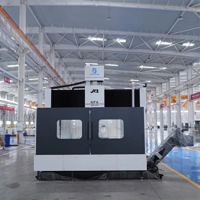
Moving Beam CNC Gantry
Product Details
Unlike a fixed-beam machine, the GFW-3860R uses a moving-beam structure. The worktable moves along the X axis, the milling head moves horizontally on the Y axis, the ram moves vertically on the Z axis, and the crossbeam itself moves vertically through the W axis. This gives the machine four controlled movement directions for large parts where the machining height changes along the workpiece. The structure is particularly relevant when comparing a moving beam cnc gantry with a fixed-beam machine, because the available vertical machining range is not determined only by the ram travel. The technical contract specifies a 2000 mm W-axis travel and 1200 mm Z-axis travel.
The spindle head uses a 420 × 420 mm fully enclosed square ram. The spindle motor, primary gearbox and second-stage gearbox are installed at the top of the ram. The spindle uses a direct-connected gear-type high/low-speed transmission, with the two BF gearboxes connected in series and the spindle driven through a high-torque coupling. An independent oil-cooling system is provided for the spindle and gearbox to remove generated heat before it transfers into the ram.
The W axis is driven by two precision preloaded ball screws, one on each side of the column. Each screw is driven by an AC servo motor through a high-ratio planetary reducer and backlash-free coupling. This arrangement is used to balance the weight of the moving crossbeam, ram and slide, while maintaining the required movement of the beam.
Product Parameters
|
Item |
Specification |
|
Model |
GFW-3860R |
|
Machine Type |
Moving Beam, Moving Table Gantry Machining Center |
|
CNC System |
SIEMENS ONE |
|
Worktable Size |
3000 × 6000 mm |
|
Maximum Table Load |
30 t |
|
T-Slot Width × Pitch |
28 × 250 mm |
|
Gantry Width |
3800 mm |
|
Spindle Nose to Table |
0–3000 mm |
|
X / Y / Z / W Travel |
6200 / 4200 / 1200 / 2000 mm |
|
X / Y / Z Rapid Traverse |
6 / 8 / 6 m/min |
|
W-Axis Rapid Traverse |
2000 mm/min |
|
Cutting Feed Rate |
1–6000 mm/min |
|
Spindle Drive |
Direct-Drive + BF Dual Gearbox |
|
Tool Holder |
BT50 |
|
Spindle Speed |
20–4000 rpm |
|
Spindle Power |
30–37 kW |
|
Spindle Torque |
1410 / 1860 N·m (Rated / Maximum) |
|
X-Axis Ball Screw |
10020 |
|
Y / Z / W Ball Screw |
8020 / 6320 / 8020 |
|
X-Axis Guideway |
3 × 55 Heavy-Duty Roller Linear Guideways |
|
Y-Axis Guideway |
2 × 55 Heavy-Duty Roller Linear Guideways |
|
Z-Axis Ram |
420 × 420 mm Fully Enclosed Square Ram |
|
W-Axis Guideway |
Hardened Box Way |
|
X / Y / Z / W Positioning Accuracy |
0.040 / 0.025 / 0.023 / 0.030 mm |
|
X / Y / Z / W Repeatability |
0.025 / 0.020 / 0.020 / 0.020 mm |
|
Electrical Requirement |
260 kVA |
|
Working Air Pressure |
6–8 kg/cm² |
|
Approx. Floor Space |
21.5 × 7 × 8 m |
The positioning and repeatability values are specified according to GB/T 19362.1-2003.
Product Features
Moving Beam + Moving Table Structure
Both the worktable and crossbeam participate in machine movement. The X axis moves the worktable, while the W axis moves the crossbeam vertically. This is different from the fixed-beam configuration used on the GFA series machines.
For large parts with changing machining heights, a moving beam cnc gantry allows the beam position to be adjusted according to the workpiece instead of relying entirely on a long Z-axis ram.
BF Dual Gearbox Spindle
The spindle uses a 30–37 kW direct-drive configuration with two BF gearboxes. The selected technical configuration specifies a 1/4.9 first-stage ratio and 1.5 second-stage variable-speed ratio. The resulting spindle range is 20–4000 rpm, with rated torque of 1410 N·m and maximum torque of 1860 N·m.
420 × 420 mm Fully Enclosed Ram
The Z-axis ram is a 420 × 420 mm fully enclosed square structure. The gearbox and second-stage reduction assembly are arranged at the upper end of the ram, while the spindle connection uses a high-torque coupling.
Independent W-Axis Drive
The W axis uses two preloaded ball screws installed on the two sides of the columns. Servo motors and planetary reducers drive the screws independently, allowing the moving crossbeam to be supported and moved through a balanced drive arrangement.
Box Guideway for W Axis
The W axis uses a rectangular hardened guideway with plastic-coated guide surfaces. This guideway arrangement supports the vertical movement of the crossbeam and its attached machining components.
Centralized Automatic Lubrication
The guideways, ball screws, gearboxes and other moving parts use a centralized automatic lubrication system. The system supplies lubrication according to preset intervals and quantities and includes protection for low oil level and pressure loss.
Product Advantages
The main reason to choose the GFW-3860R over a conventional fixed-beam machine is the additional W-axis movement. The crossbeam has a 2000 mm travel, while the ram provides another 1200 mm of Z-axis travel. This gives the machine more flexibility when the height of the workpiece or the required spindle position changes.
The 30-ton table capacity is also suited to heavy components. The 3000 × 6000 mm table provides a long loading surface, while the 6200 mm X-axis travel allows the spindle to cover most of the table length without requiring repeated repositioning of the workpiece.
The spindle is configured for torque rather than very high rotational speed. With up to 1860 N·m maximum torque, the direct-drive + BF dual-gearbox arrangement is intended for large-part milling and boring operations where cutting load is significant.
The W-axis drive is another practical difference. Instead of using a single drive to move the entire crossbeam, two independently driven ball screws are positioned on the left and right sides. The planetary reducers and backlash-free couplings help coordinate the movement of the beam and its attached machining components.


Product Applications
The GFW-3860R is designed for large components requiring several machining operations without moving the workpiece between different machines.
General & Construction Machinery
Suitable for large machine bases, structural frames, housings and heavy mechanical components.
Power & Energy Equipment
Used for large equipment bases, housings and structural parts where high spindle torque and a large machining envelope are required.
Automotive Manufacturing
Applicable to large tooling, structural components and production equipment parts.
Mold Manufacturing
The large X/Y working range and adjustable beam height can be used for large mold bases and mold structures.
Civil Aviation
Suitable for machining large aircraft structural components and related fixtures.
Shipbuilding
The 6000 mm table length and 30-ton capacity provide a working platform for large marine components.
Rail Transportation
Can be used for long structural parts, frames and other large mechanical components.
The technical contract lists general machinery and engineering machinery, automotive manufacturing, power and energy equipment, mold processing, civil aviation, shipbuilding and rail transportation as application fields.
Customization Options
The GFW-3860R already has a relatively extensive configuration list, so customization can focus on the machining process rather than simply changing basic dimensions.
A 40T vertical/horizontal tool magazine is included in the selected configuration.
The selected configuration includes:
- Fully automatic right-angle milling head with head magazine
- Fully automatic universal milling head
- Fully automatic extension milling head
These heads allow the machine to be configured for different machining directions and deeper or less accessible surfaces.
The selected options include:
- Four-axis linear scales
- Renishaw laser tool setter and probe
These can be used where the machining process requires additional position measurement and tool/workpiece inspection.
The standard selected spindle configuration is:
- 30–37 kW
- Direct drive
- BF dual gearbox
- 1/4.9 + 1.5 two-stage transmission
- BT50
- 20–4000 rpm
A 7 MPa spindle center coolant system is also included in the selected configuration.
The machine uses SIEMENS ONE. The selected configuration includes a 22-inch color touchscreen, Russian-language interface support, wireless handwheel, USB and RJ-45 interfaces, as well as air and water guns.
Packaging & Logistics
Because the GFW-3860R is a large moving-beam machine with an approximate overall footprint of 21.5 × 7 × 8 m, transportation needs to be planned around the workshop access, road conditions, lifting equipment and final installation position.
The machine is prepared for shipment according to the actual transport arrangement. Large structural components are handled separately where required, with the shipment organized according to the packing list and installation sequence.
Before shipment, the buyer and seller confirm:
Transportation route and available road conditions
Maximum transport dimensions of major components
Workshop entrance and lifting height
Unloading and positioning method
Required lifting equipment
Foundation and secondary grouting preparation
Power and compressed-air connections
The installation document specifies that the heaviest lifting component is approximately 30 tons, and the customer should prepare lifting equipment with a rated capacity of at least 30 tons.
The buyer is responsible for unloading, lifting and positioning at the factory. The manufacturer provides on-site inspection, installation, commissioning and acceptance after the machine arrives.
For compressed air, the required pressure is 0.6–0.8 MPa, with clean and dry air required for the machine's pneumatic system.
Installation & After-Sales Support
Installation and Commissioning
The buyer should complete the foundation according to the manufacturer's supplied foundation drawing before the machine arrives. This is particularly important for a large moving-beam machine because the installation condition directly affects the subsequent machine accuracy.
After delivery, the manufacturer carries out on-site inspection, installation, commissioning and acceptance with the customer's cooperation.
Acceptance
The acceptance process consists of pre-acceptance at the manufacturer's facility and final acceptance at the customer's factory. The final stage is carried out after installation and commissioning and focuses on the agreed machining accuracy and technical requirements.
The technical contract also contains inspection items for X/Y/W movement accuracy, perpendicularity, table flatness and parallelism, spindle runout and spindle-axis alignment.
Training and Warranty
Operator training is provided at the customer's factory after installation and commissioning, covering operation and routine maintenance.
The warranty period is 12 months from final acceptance. During the warranty period, manufacturing- or design-related failures under normal operating conditions are covered according to the technical agreement. After the warranty period, online technical support and technical guidance remain available, with spare parts supplied at preferential prices.
Actual Shipment Photo

Factory Showcase

Hot Tags: moving beam CNC gantry, China moving beam CNC gantry manufacturers, suppliers, factory
You Might Also Like



Send Inquiry