



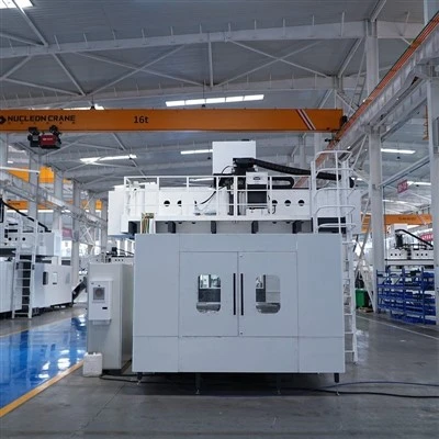
CNC Gantry Type Machining Center
Product Details
The X-axis of cnc gantry type machining center utilizes a dual-motor rack-and-pinion drive system with backlash compensation. Each side of the bed is equipped with an M5-grade hardened and ground rack; the dual-motor drive, combined with a pre-loaded backlash elimination mechanism, ensures minimal reversal backlash. The Y-axis crossbeam employs a stepped right-angle guideway layout, with guideways positioned on both the vertical and top surfaces to independently bear horizontal cutting forces and the vertical weight of the ram. The Z-axis features a 500×500 mm fully enclosed square ram with a hardened guideway structure; the guideways are hardened, while the pressure plates and gibs are lined with low-friction composite material (Turcite). The X-axis bed is equipped with three heavy-duty size-55 roller guideways, and the Y-axis features two heavy-duty size-55 roller guideways.
Product Specifications
|
Item |
Unit |
GMD53120R |
GMD53160R |
GMD53200R |
|
Box-type Ram |
||||
|
Worktable |
||||
|
Worktable Dimensions |
mm |
4200×12000 |
4200×16000 |
4200×20000 |
|
Worktable Load Capacity |
T |
15000 kg/m² |
15000 kg/m² |
15000 kg/m² |
|
T-slot Width × Pitch |
mm |
28×250 |
28×250 |
28×250 |
|
Machining Range |
||||
|
Travel Range (X / Y / Z) |
mm |
12500×6000×1500 |
16500×6000×1500 |
20500×6000×1500 |
|
Gantry Width |
mm |
5300 |
5300 |
5300 |
|
Distance from Spindle Nose to Table Surface |
mm |
500-2000 |
500-2000 |
500-2000 |
|
Feed Rate |
||||
|
Rapid Feed Rate (X / Y / Z) |
m/min |
40461 |
40461 |
40461 |
|
Cutting Feed Rate |
mm/min |
1-6000 |
1-6000 |
1-6000 |
|
Spindle Specifications |
||||
|
Tool Holder Type |
- |
BT50 |
BT50 |
BT50 |
|
Spindle Speed Range |
rpm |
20-4500 |
20-4500 |
20-4500 |
|
Spindle Power |
kW |
30 |
30 |
30 |
|
Spindle Drive Type |
- |
Standard Configuration: Direct-Drive + BF Gearbox |
Standard Configuration: Direct-Drive + BF Gearbox |
Standard Configuration: Direct-Drive + BF Gearbox |
|
Drive System |
||||
|
Drive Specifications (X / Y / Z) |
- |
Module 5 Rack and Pinion / 8020 / 6320 |
Module 5 Rack and Pinion / 8020 / 6320 |
Module 5 Rack and Pinion / 8020 / 6320 |
|
Guideway Specifications (X / Y / Z) |
- |
The X-axis is equipped with 4×55 heavy-duty roller linear guideways, and the Y-axis with 3×55 heavy-duty roller linear guideways. The Z-axis comes standard with a fully enclosed 500×500 mm box-type ram. |
||
|
Machine Accuracy |
||||
|
Positioning Accuracy (X / Y / Z) |
mm |
0.055/0.038/0.025 |
0.065/0.038/0.025 |
0.072/0.038/0.025 |
|
Repeatability (X / Y / Z) |
mm |
0.033/0.038/0.027 |
0.038/0.038/0.027 |
0.046/0.038/0.027 |
|
Others |
||||
|
Air Supply Pressure |
MPa |
0.6~0.8 |
0.6~0.8 |
0.6~0.8 |
|
Electrical Capacity |
kVA |
170 |
170 |
170 |
|
Overall Dimensions |
m |
20.5×8.5×6.9 |
24.5×8.5×6.9 |
2.5×8.5×6.9 |
Product Features
Major castings-including the bed, columns, and crossbeam-undergo two heat treatment stages after casting: initial annealing to relieve casting stresses, followed by aging treatment to stabilize the microstructure. This process minimizes long-term deformation during operation and ensures the geometric accuracy of the guideway surfaces is maintained over an extended period.
Given the maximum X-axis travel of 20.5 meters, ball screw drives are impractical due to issues like sagging and vibration over such lengths. Instead, a rack-and-pinion drive is used, featuring M5-grade hardened and ground racks on both sides of the bed; the hardened tooth surfaces offer superior wear resistance. The X-axis utilizes a dual-motor drive system; the two motors are preloaded with a half-pitch offset via a backlash-elimination mechanism to eliminate gear backlash. This ensures zero dead travel during direction reversals and prevents vibration during milling.
The guideways on the crossbeam feature a stepped right-angle layout, with rails mounted on both the vertical and top surfaces. During milling, horizontal cutting forces are borne by the vertical guideways, while the dead weight of the ram and saddle is supported by the top guideways. With each set of guideways performing a specific function-avoiding the scenario where a single rail bears loads from two directions simultaneously-movement is significantly smoother.
The Z-axis employs a 500×500mm fully enclosed square ram; this four-sided closed structure offers superior rigidity compared to open C-type rams. The guideways undergo hardening treatment for high hardness and wear resistance, while clamping plates and gibs feature bonded plastic liners (providing lubrication and friction reduction). When the ram extends 1,500mm for machining, the contact rigidity of the hardened guideways outperforms that of roller guideways, resulting in minimal tool chatter during heavy-duty cutting.
Components such as the crossbeam, ram, spindle head, and Y-axis drive system are interchangeable across the three specifications of the GMD53 series (featuring 12m, 16m, and 20m tables). This allows users to interchange parts between different machine sizes, eliminating the need to stock separate sets of spare parts for each model.


Product Applications
Marine Diesel Engine Blocks:
The 12–20m machining range accommodates various models of marine main engines. Machining requirements include cylinder bore faces, main bearing bores, and side mounting surfaces-tasks involving long, heavy workpieces. The stationary table design eliminates inertia issues associated with moving workpieces, ensuring safer machining operations.
Wind Turbine Blade Molds:
Blade molds are elongated structures, often exceeding 16 meters in length. The mold surfaces are complex contours requiring 3-axis simultaneous milling. The X-axis travel of 20,500mm covers the entire length of the mold, while the 1,500mm Z-axis travel meets the depth requirements of the mold cavity.
Marine engineering structural components:
Examples include extra-long welded parts such as drilling platform legs and jacket nodes, which require overall surface milling and boring after welding. With a table width of 4,200 mm and a gantry width of 5,300 mm, the machine can accommodate large tubular structures.
Large machine tool beds:
The machine tool manufacturing industry itself requires the machining of beds and columns ranging from 10 to 20 meters in length; the travel range and table dimensions of the GMD53 series are ideally suited to these requirements.
FAQ
1. How should the equipment be transported?
The GMD53 series consists of extra-long and heavy equipment; transporting the machine as a single unit is impractical. Sectional transport is typically used: the bed is shipped in segments, the crossbeam and columns are disassembled, and the ram and spindle head are packaged separately. We provide sectional packaging plans and transport bracket designs based on the equipment dimensions. You must verify the clearance dimensions of factory roads and workshop doors in advance to ensure transport vehicles can access the unloading area. We recommend selecting a logistics company experienced in transporting large-scale equipment.
2. What is the delivery lead time?
The production cycle is approximately 150–180 days following contract signing and receipt of the down payment. Casting the bed segments and performing aging treatment takes 60–75 days; guideway grinding and rack installation take about 30 days; and assembly and commissioning of the complete machine take about 45 days. There is little difference in lead time between the three specifications (12m, 16m, and 20m); the schedule depends primarily on casting production planning. The specific delivery date will be confirmed in the contract.
3. What are the requirements for unloading upon arrival?
After the equipment arrives in sections, overhead cranes or mobile cranes with sufficient lifting capacity are required for unloading and assembly. The heaviest single components are the bed segments or the crossbeam, weighing approximately 25–35 tons; exact weights will be provided prior to shipment. You must prepare lifting equipment (a capacity of at least 50 tons is recommended), an unloading area (with a hardened surface), and a temporary storage site in advance. The manufacturer will dispatch installation personnel to the site to supervise assembly and positioning.
Photo with the client

Factory Showcase

Hot Tags: CNC gantry type machining center, China CNC gantry type machining center manufacturers, suppliers, factory
You Might Also Like



Send Inquiry