



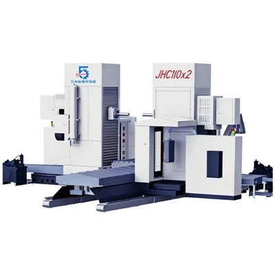
Floor Type Boring and Milling Machine
Product Overview
The Floor Type Boring and Milling Machine is developed for manufacturers that need to machine large, long, and heavy components with demanding boring and milling requirements. Its floor-type machining configuration provides an open working area for oversized workpieces, while the horizontal spindle arrangement allows efficient access to deep holes, mounting surfaces, and other critical features.
The JHC and JFB series cover multiple machine configurations, including JHC110B×2, JHC130B×2, JHC130×2, JHC160×2, JFB130Z×2, and JFB160Z×2. The available spindle diameters range from 110 mm to 160 mm, while the X-axis machining range can extend from 3,000 mm to 20,000 mm, making the machine suitable for both medium-large and extremely long workpieces.
The machine integrates boring and milling operations into a single machining platform and can be equipped with different milling heads, CNC systems, and tool magazine capacities according to the production process. It is suitable for heavy equipment manufacturing, construction machinery, mining equipment, energy equipment, large industrial machinery, and other applications involving large components.
Large-Part Machining Capability
Large workpieces often require more than a conventional machining center can provide. Limited table dimensions, insufficient travel, or restricted workpiece access can result in additional setups and repositioning.
The floor-type configuration addresses these requirements by providing an extended machining envelope and flexible workpiece positioning. Depending on the configuration, the X-axis travel ranges from 3,000 to 6,000 mm or 6,000 to 20,000 mm, while the available worktable length can be configured from 3,000 to 6,000 mm or according to an extended 6000 + n×1000 mm arrangement.
This configuration makes the machine particularly suitable for long machine beds, large welded structures, heavy equipment frames, and other components requiring machining over an extended length.
Horizontal Boring and Milling in One Machine
The machine is designed to handle multiple machining processes within the same production system. Depending on the selected tooling configuration, operations can include:
Horizontal boring
Milling
Drilling
Tapping
Reaming
Face machining
Large-hole machining
Multi-surface machining
Combining these operations can reduce the number of workpiece transfers between machines. For large components, this can also help simplify setup procedures and maintain more consistent positioning throughout the machining process.
Spindle and Cutting Configuration
The series offers spindle diameters of 110 mm, 130 mm, and 160 mm, allowing users to select a configuration according to workpiece size, machining requirements, and cutting conditions.
The spindle uses an ISO 50 taper and operates within a 10–2,000 rpm speed range. Different motor power and torque configurations are available across the models, providing options for applications ranging from general machining to demanding heavy-duty cutting.
The machine can also be equipped with different milling heads, including vertical milling heads, universal milling heads, extended spindle heads, flat heads, and other optional head configurations. This gives manufacturers greater flexibility when machining surfaces located at different orientations.
Extended Working Range
The machine is designed around the requirements of large-scale component production. Different axis configurations provide flexibility for positioning the spindle and machining head relative to the workpiece.
The available Y-axis travel ranges from 1,600 to 4,000 mm, while Z-axis travel is available from 1,000 to 2,000 mm depending on the model group. The W-axis travel reaches 600 or 800 mm.
This combination of longitudinal and vertical movement allows the machining head to access different areas of large workpieces while maintaining a practical machining layout.
Technical Specifications
|
Parameter |
JHC110B×2 |
JHC130B×2 |
JHC130×2 |
JHC160×2 |
JFB130Z×2 |
JFB160Z×2 |
|
Spindle Diameter |
110 mm |
130 mm |
130 mm |
160 mm |
130 mm |
160 mm |
|
Spindle End Diameter |
221.44 mm |
221.44 mm |
221.44 mm |
260 mm |
221.44 mm |
260 mm |
|
Spindle Taper |
ISO 50 |
ISO 50 |
ISO 50 |
ISO 50 |
ISO 50 |
ISO 50 |
|
Spindle Speed |
10–2,000 rpm |
10–2,000 rpm |
10–2,000 rpm |
10–2,000 rpm |
10–2,000 rpm |
10–2,000 rpm |
|
Spindle Motor Power |
15/19.5 kW |
15/19.5 kW |
30/25 kW |
30/31 kW |
31/37 kW |
44/45 kW |
|
Maximum Spindle Torque |
1,430/1,620 Nm |
1,430/1,620 Nm |
2,490/2,080 Nm |
2,490/2,570 Nm |
2,570/3,070 Nm |
3,650/3,740 Nm |
|
Maximum Spindle Axial Thrust |
15,000 N |
15,000 N |
20,000 N |
20,000 N |
25,000 N |
25,000 N |
|
Ram Cross-Section |
360×400 mm |
360×400 mm |
400×450 mm |
400×450 mm |
460×520 mm |
460×520 mm |
|
Ram Length |
280 mm |
280 mm |
500 mm |
500 mm |
- |
- |
|
X-Axis Travel |
3,000–6,000 mm |
3,000–6,000 mm |
3,000–6,000 mm |
3,000–6,000 mm |
6,000–20,000 mm |
6,000–20,000 mm |
|
Y-Axis Travel |
1,600/2,000 mm |
1,600/2,000 mm |
2,000/2,500/3,000 mm |
2,000/2,500/3,000 mm |
2,500/3,000/4,000 mm |
2,500/3,000/4,000 mm |
|
Z-Axis Travel |
1,600 mm |
1,600 mm |
2,000 mm |
2,000 mm |
1,000 mm |
1,000 mm |
|
W-Axis Travel |
600 mm |
600 mm |
800 mm |
800 mm |
800 mm |
800 mm |
|
Table Width |
1,200/1,400/1,600 mm |
1,200/1,400/1,600 mm |
1,200/1,400/1,600 mm |
1,200/1,400/1,600 mm |
1,400/1,600/2,000 mm |
1,400/1,600/2,000 mm |
|
Table Length |
3,000–6,000 mm |
3,000–6,000 mm |
3,000–6,000 mm |
3,000–6,000 mm |
6,000+n×1,000 mm |
6,000+n×1,000 mm |
|
Maximum Table Load |
According to table dimensions |
According to table dimensions |
According to table dimensions |
According to table dimensions |
According to table dimensions |
According to table dimensions |
|
Rapid Traverse X/Y/Z/W |
10,000 mm/min |
10,000 mm/min |
10,000 mm/min |
10,000 mm/min |
10,000 mm/min |
10,000 mm/min |
|
Cutting Feed X/Y/Z/W |
8,000 mm/min |
8,000 mm/min |
8,000 mm/min |
8,000 mm/min |
8,000 mm/min |
8,000 mm/min |
|
Positioning Accuracy X |
0.015 mm/m |
0.015 mm/m |
0.015 mm/m |
0.015 mm/m |
0.015 mm/m |
0.015 mm/m |
|
Positioning Accuracy Y/Z |
0.012 mm/m |
0.012 mm/m |
0.012 mm/m |
0.012 mm/m |
0.012 mm/m |
0.012 mm/m |
|
Positioning Accuracy W |
0.015 mm/full length |
0.015 mm/full length |
0.015 mm/full length |
0.015 mm/full length |
0.015 mm/full length |
0.015 mm/full length |
|
Repeatability X |
0.012 mm |
0.012 mm |
0.012 mm |
0.012 mm |
0.012 mm |
0.012 mm |
|
Repeatability Y/Z |
0.010 mm |
0.010 mm |
0.010 mm |
0.010 mm |
0.010 mm |
0.010 mm |
|
Repeatability W |
0.012 mm |
0.012 mm |
0.012 mm |
0.012 mm |
0.012 mm |
0.012 mm |
|
Two-Spindle Centerline Parallelism |
Φ0.05/1000 mm |
Φ0.05/1000 mm |
Φ0.05/1000 mm |
Φ0.05/1000 mm |
Φ0.05/1000 mm |
Φ0.05/1000 mm |
|
Y-Axis Guideway |
Linear / Hardened Guideway |
Linear / Hardened Guideway |
Linear / Hardened Guideway |
Linear / Hardened Guideway |
Linear / Hardened Guideway |
Linear / Hardened Guideway |
|
CNC Control System |
FANUC 0i / SIEMENS 828D |
FANUC 0i / SIEMENS 828D |
FANUC 0i / SIEMENS 828D |
FANUC 0i / SIEMENS 828D |
FANUC 0i / SIEMENS 828D |
FANUC 0i / SIEMENS 828D |
|
Optional CNC System |
FANUC 31i / SIEMENS ONE |
FANUC 31i / SIEMENS ONE |
FANUC 31i / SIEMENS ONE |
FANUC 31i / SIEMENS ONE |
FANUC 31i / SIEMENS ONE |
FANUC 31i / SIEMENS ONE |
|
Milling Head Options |
Vertical, Universal, Extended Spindle, Flat Head, etc. |
Same |
Same |
Same |
Same |
Same |
|
Tool Magazine |
40 Tools, Optional 60/80/100 |
40 Tools, Optional 60/80/100 |
40 Tools, Optional 60/80/100 |
40 Tools, Optional 60/80/100 |
40 Tools, Optional 60/80/100 |
40 Tools, Optional 60/80/100 |
Applications
The Floor Type Boring and Milling Machine can be applied to large-component manufacturing where conventional machining centers may not provide sufficient travel or working space.
Typical applications include:
Heavy machinery:
Machine beds, frames, housings, bases, and structural components.
01
Construction equipment:
Large components for excavators, cranes, loaders, drilling machines, and other heavy equipment.
02
Mining machinery:
Large housings, support structures, frames, and heavy-duty mechanical components.
03
Energy equipment:
Large parts used in power generation and industrial energy systems.
04
General engineering:
Customized large mechanical components, welded structures, and industrial equipment parts.
05
Typical Workpieces
Depending on the selected configuration, the machine can be used for large machine bases, gearbox housings, pump bodies, valve bodies, heavy equipment frames, mining machinery components, energy equipment parts, welded structures, and other oversized industrial components.
The extended table configuration is particularly useful for long workpieces that require machining across multiple sections without repeatedly moving the component to different machines.
Tooling and Automation
Different machining requirements can be addressed through optional milling head configurations. Customers can select a vertical milling head, universal milling head, extended spindle head, flat head, or another suitable head according to the required machining process.
The machine is equipped with a 40-tool magazine, with optional 60-, 80-, or 100-tool configurations available for applications involving a wider range of machining operations.
For CNC control, the standard options include FANUC 0i and SIEMENS 828D, while FANUC 31i and SIEMENS ONE dual-channel CNC systems can also be selected according to the production requirements.
How to Select the Right Machine
The correct Floor Type Boring and Milling Machine should be selected according to the workpiece rather than based on a single specification.
Before requesting a quotation, customers should prepare:
Workpiece dimensions
Workpiece weight
Material
Production volume
Maximum hole diameter
Required boring and milling operations
Required machining accuracy
Machining area and working range
Preferred CNC control system
Workpiece drawings or sample components
This information allows the machine configuration to be matched more accurately to the actual machining process.
Customized Machining Solutions
Large-part machining requirements can vary considerably between manufacturers. The machine can therefore be configured around the customer's workpiece dimensions, machining processes, tooling requirements, accuracy targets, and production environment.
Options can include different spindle configurations, milling heads, table dimensions, tool magazine capacities, CNC systems, and other auxiliary equipment.
Providing a detailed workpiece drawing is recommended when requesting a machine proposal, especially for applications involving oversized components or complex machining surfaces.
FAQ
What is a Floor Type Boring and Milling Machine?
It is a heavy-duty CNC machine designed for machining large and complex workpieces through boring, milling, drilling, and related machining operations.
What is the maximum X-axis travel?
Depending on the model, the X-axis travel ranges from 3,000–6,000 mm to 6,000–20,000 mm.
What spindle diameters are available?
The JHC and JFB configurations shown in this series provide spindle diameters of 110 mm, 130 mm, and 160 mm.
Which CNC systems are available?
The machine can use FANUC 0i or SIEMENS 828D, with optional FANUC 31i or SIEMENS ONE dual-channel CNC systems.
Can the machine be customized?
Yes. Machine dimensions, spindle configuration, milling head, table arrangement, tool magazine capacity, CNC system, and other configurations can be selected according to the actual machining application.
Request a Quote
Looking for a Floor Type Boring and Milling Machine for large, long, or heavy components?
Send us your workpiece drawing, dimensions, weight, material, machining requirements, and accuracy requirements. Our engineering team can evaluate your application and recommend a suitable configuration from the JHC or JFB series.
Actual Shipment Photo

Factory Showcase

Hot Tags: floor type boring and milling machine, China floor type boring and milling machine manufacturers, suppliers, factory
You Might Also Like




Send Inquiry